Possible Measurement Objects:
Further applications include:
Benefits:
Legally Reliable Results
Based on the reference values for a pole in its installed condition and the maximum permissible limit values for the dynamic parameters required to ensure structural stability, compared with the actual measured values, a clear assessment of structural stability and condition classification can be carried out.
Here you can find information on the legal framework and responsibilities of facility operators.
This method was developed to assess the structural and positional stability of engineering structures that exhibit pronounced dynamic behaviour and vibration characteristics (e.g. lighting poles, bridges, high-rise buildings, retaining walls, towers, noise barriers, etc.).
The dynamic behaviour of a structure is described and evaluated by its natural frequency, mode shape, and damping characteristics.
Facility operators are required to provide periodic proof of structural stability for poles and similar structures. Liability rests with the owner or operator in accordance with the applicable legal obligations relating to public safety, infrastructure maintenance, and structural liability.
Structural load-bearing capacity and positional stability must be inspected and documented in accordance with the current state of the art and applicable engineering standards.
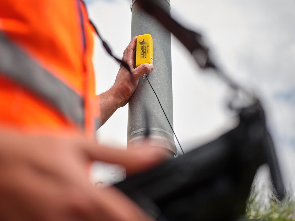
In the testing procedure for verifying the structural and positional stability of lighting poles, cantilever poles, and guyed poles made of steel, aluminium, or concrete, a highly sensitive two-dimensional vibration sensor is attached to the pole shaft.
The structure is excited into vibration in both spatial directions, offset by 90 degrees to each other, by means of a sequence of hammer impacts using a rubber hammer at predefined time intervals.
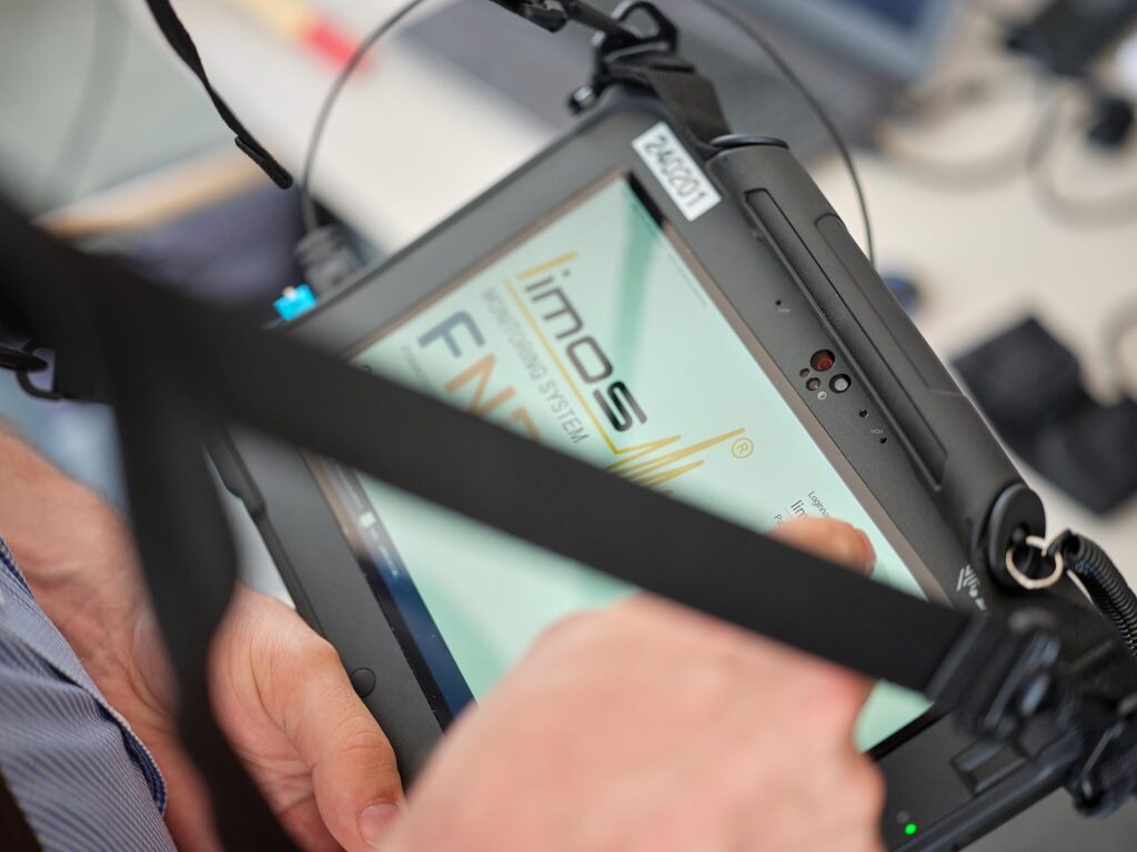
During the measurement process, the signals recorded by the vibration sensor are supplemented with temperature data, GPS coordinates of the measurement location, as well as the name (identification number) and photographs of the measurement object. All collected information is stored in a measurement data file for further analysis and documentation.
In the second stage of the assessment, the load-bearing capacity of the respective pole or pole type is verified in accordance with the applicable standards (DIN EN 40 and the relevant national annexes). Using finite element analysis (FEA) software, a structural model of the pole is created, and both static and dynamic recalculations are performed based on the measured data.
As specified by the applicable standards, the prescribed loads and load combinations are applied to the structural model. Subsequently, stress verification and fatigue strength verification are carried out at the standard-defined critical locations.
The model is then analysed with regard to its dynamic (vibration) characteristics, and the calculated results (i.e. the target dynamic characteristics) are stored in the CBR database as the reference condition for an undamaged pole.
In the subsequent step, the computational model is used to simulate cross-sectional reductions due to corrosion, cracks, and other defects at critical locations. These simulations are continued until the stress and fatigue verifications reach the maximum permissible values defined by the applicable standards.